Quick Contact>

Hotline

0731-85260926 18665876229

中文
Power Transistor Curve Tracer Semiconductor Parameter Analyzer SMU Source Measure Unit Dynamic Parameter Test System CV Parameter Tester Gate Charge (Qg) Tester WAT Wafer Acceptance Test System TLP Transmission Line Pulse EMMI Low-Light Infrared Fault Localization HCI/BTI/TDDB/EM effects Femtoammeter/Electrometer/High Resistance Meter High and low temperature electrical performance simulation H3TRx Customizable System Integration Software
Standard Manual Probe Station Portable Desktop Probe Station Semi-automatic probe station RF/Microwave Probe Station High/Low Temperature Probe Station Vacuum cryogenic probe station system Wafer electrical parameter test system Strong Magnetic - Hall Probe Station Custom Precision Probe Card High/Low Temperature Chuck System (Taiko) Magnetic Probe Holder CCD Microscope Test cables and adapter fixtures Shielded Box and Vibration Isolation Table Probes and other accessories
B-H Analyzer Magnetic Loss Power Tester Impedance Analyzer DC Bias High-Frequency LCR Meter Vector Network Analyzer VNA Frequency Response Analyzer Milliohm Meter / Battery Internal Resistance Tester
Rapid Temperature Change Thermal Flow Meter Device High/Low Temperature Platform Thermalplate Device junction temperature simulator Tj
12-bit high-definition digital oscilloscope Optically Isolated Oscilloscope System Basic Digital Oscilloscope Signal generator Digital Multimeter DMM Spectrum Analyzer Frequency counter Infrared thermal imager
Optically isolated voltage probe Optically Isolated Current Probe Dynamic On-Resistance Rds(on)dynamic Oscilloscope voltage probe High-voltage differential probe Fluxgate current transformer AC/DC Current Probe Non-inductive coaxial shunt Communication Interfaces and Cables Dedicated fixture Software
Multi-channel data acquisition instrument Data Acquisition and Playback Power Analyzer
Digital Phase-Locked Loop Amplifier Ultra-Low Noise Preamplifier Precision Current Amplifier Precision Differential Amplifier Precision Filter Light chopper Precision Low-Noise DC Power Supply
Programmable DC Power Supply DC Electronic Load Precision Bipolar Power Amplifier Bipolar simulation power supply
Safety Tester (ACI/DCI/IR/GB) High-voltage meter HV meter
Standard or calibration source meter Standard current and voltage meters

Technical Services & Solutions

Technical support and after sales service

Technical Services & Solutions

3.3kV devices for SST solid-state transformers are arriving in force—how does their static testing differ from that of 1.2kV devices?

Published: 2026-04-17 Views: 次

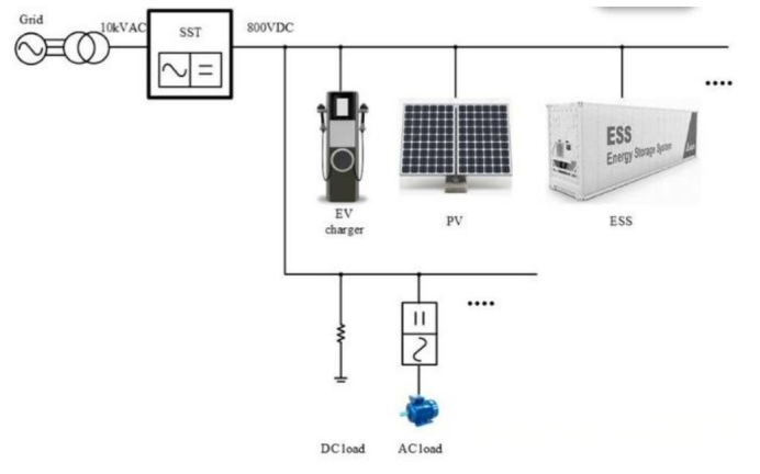
Microsoft CEO Satya Nadella recently said that despite sustained high demand for AI chips, Microsoft is not facing a compute surplus—rather, its data centers are nearing the limits of available power and physical space.
NVIDIA CEO Jensen Huang has likewise noted that the industry will not see a compute surplus over the next two to three years. As AI compute scales exponentially, power demand rises sharply as well. The solid-state transformer (SST) is regarded as one of the key pieces to solving this "power anxiety."


With this industry trend gathering momentum, medium-voltage grids, rail transit, energy storage, and high-voltage charging are advancing rapidly, and 3.3kV power devices (SiC MOSFETs/IGBTs) are now commonplace.
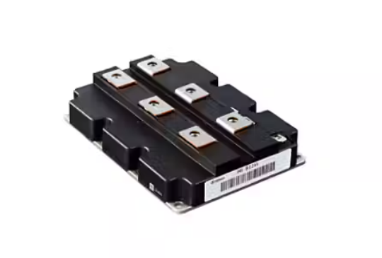
Beyond the partial discharge (PD) and insulation topics everyone is discussing, the static testing of SSTs also differs substantially from that of earlier 1.2kV automotive-grade devices.
To deploy 3.3kV devices in an SST, room-temperature static test equipment rated at 3kV is simply not enough.

1. Three Hard Requirements SSTs Place on 3.3kV Devices

1. Withstand voltage must retain adequate safety marginIn real operating conditions, 3.3kV devices are subjected to overvoltage, spikes, and turn-off overshoot, so breakdown, current, and reliability must be verified above the rated voltage. At minimum, the instrument must deliver 1.2× the device's 3.3kV rating—that is, 3.96kV.


2. High-current characteristics determine efficiency and thermal designSSTs pursue high power density with fewer links, making the star configuration the preferred choice today—which means higher current ratings. On-state voltage drop, on-resistance, output characteristics, and the SOA (safe operating area) at high current therefore become the core basis for circuit design.


3. High-temperature parameter drift directly determines system reliabilityHigh-density integration causes significant module temperature rise, and threshold voltage, on-resistance, leakage current, and breakdown voltage all vary with junction temperature. Room-temperature data is only a reference; high-temperature behavior reflects real-world performance.

2. Two Critical Shortcomings of Existing Equipment

1. A gap in voltage ranges—mainstream equipment offers only 3kV / 10kV:

  • 3kV: below the 3.3kV rating, so margin and reliability verification are impossible;
  • 10kV: costly, requires an extra option, bulky, and overkill—not economical.

2. Room-temperature testing only—no real operating conditions


At high temperature, leakage current surges, on-resistance rises, and Vth shifts; room-temperature data alone cannot assess the real operating risks of an SST.


3. Iwasaki CS‑5400: A Precise Match for 3.3kV Testing

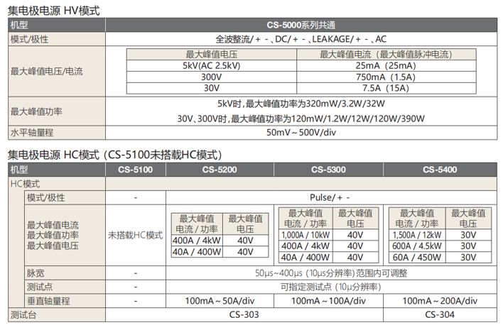
5000V / 1500A is the most sensible test configuration for today's 3.3kV devices:
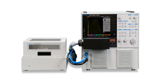
  • 1. 5000V coverage: more than 1.5× the device's 3.3kV rating, enabling rated testing, breakdown evaluation, and high-precision leakage current measurement;
  • 2. Still delivers up to 25mA at 5000V, ensuring leakage testing capability for high-voltage power devices at high temperature;
  • 3. 1500A supports both discrete devices and modules: high-current output characteristics, Vce(sat), Rds(on), and SOA verification;

4. Pairing with the PHS High-Temperature System Completes the Solution

The CS‑5400 plus the PHS high-temperature test system truly meets SST test requirements:
  • 1. Temperature range: RT to 175℃, with precise control and minimal fluctuation; for low-temperature testing, pair with a thermal stream system (covering -40 to 300℃) or a probe station with a hot chuck.


  • 2. Supports both modules and discrete devices; heating does not interfere with the test loop, ensuring accurate IV, leakage current, and breakdown voltage measurements;


  • 3. Automated multi-temperature-point testing with one-click datasheet-grade reports;

  • 4. Complies with AEC‑Q101, AQG‑324, and JEDEC reliability test standards.
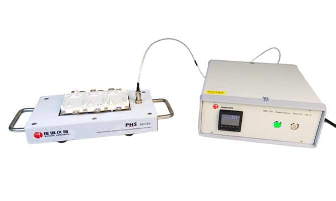
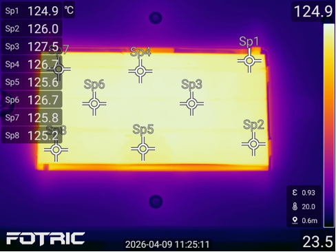
(High-temperature test fixture for power modules)
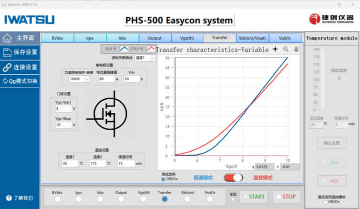

                                                                      (Transfer characteristic Vgs-Id curve)


Capabilities include:
Threshold voltage: V(th), Vge(th) at room/high temperature
Transfer characteristics: Id-Vgs, Ic-Vge at room/high temperature