 Technical Support
 Feedback


1. Background
In the development and production testing of power semiconductor modules (IGBT, SiC MOSFET, etc.)—and especially in the validation of automotive-grade power modules—high-power transfer characteristic (IV) testing is a core step for evaluating a device's conduction capability, rated current, and reliability. The transfer curve is the key basis for judging device performance and consistency.
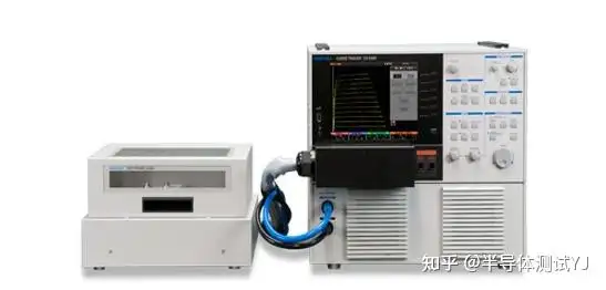
The IWATSU CS-5400 power device analyzer is a high-end high-power test instrument rated at 12 kW maximum peak power, 1500 A maximum peak current, and 5 kV maximum test voltage. It is fully suited to the complete test requirements of automotive-grade high-voltage, high-power modules (such as automotive SiC MOS modules and IGBT modules).
A recent technical support case is typical: a customer was using the CS-5400 to test an automotive-grade high-power module. With Vds set to 20 V for transfer characteristic testing, the drain current Id remained below 200 A—far below the instrument's full-power output capability (12 kW/20 V = 600 A) and well short of the rated-current validation required for automotive-grade modules. The customer had already optimized the test wiring (short, thick cables, screw-fastened connections), ruling out contact resistance. Subsequent attempts to shorten the pulse width, reduce the number of test points, and adjust test point positions all failed to raise the current. The issue was finally resolved by setting the pulse width to 400 μs and selecting test points in the smooth region of the transfer curve, which successfully produced close to 600 A—the instrument's full-power level—meeting the accuracy and reliability requirements of automotive-grade testing.
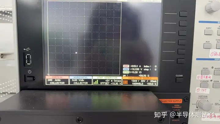
This article breaks down the root cause from four angles—the instrument's operating principle, pulsed power output characteristics, the core value of the transfer curve, and the necessity of automotive-grade testing—explains the key significance of comparing transfer curves at room and high temperature, and summarizes practical techniques for high-power IV testing (including automotive scenarios) as an actionable reference for similar tests.
2. Fundamentals: Why the Transfer Curve Matters (Core Basis for Automotive-Grade Testing)
The transfer characteristic curve (Id-Vgs) is the most important electrical characteristic curve of a power module (IGBT, SiC MOSFET). It directly reflects how the gate-source voltage Vgs controls the drain current Id. Its importance spans two scenarios and is indispensable in automotive-grade testing in particular:
2.1 Core Value of the Transfer Curve (General Scenarios)
Assessing conduction capability: the curve slope and saturation current indicate whether the device can reach its rated current—a core metric for verifying device performance.
Judging device consistency: in volume testing, comparing transfer curves across many devices screens out outliers with excessive curve shift or fluctuation, ensuring production consistency.
Detecting device defects: abnormal inflection points, nonlinear jumps, or excessive leakage on the curve directly point to gate oxide defects, junction damage, and similar issues.
Supporting parameter selection: the smooth-region range and saturation current on the curve help match gate voltage and current requirements to the actual application, optimizing circuit design.
2.2 Why the Transfer Curve Is Essential in Automotive-Grade Module Testing
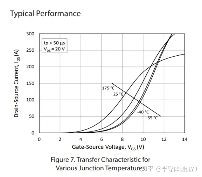
Automotive-grade power modules (used in on-board OBC, DC/DC, and drive motors) must withstand extreme temperatures from -40°C to 175°C, high-frequency switching stress, and high-voltage surges. The transfer curve is a core basis for automotive-grade reliability validation and meets automotive standard requirements:
Automotive-grade devices must pass "full-temperature-range transfer curve testing" to verify conduction capability at temperature extremes and ensure stable operation under in-vehicle conditions.
The smoothness and stability of the transfer curve directly determine switching loss and thermal stability, which affect vehicle range and safety.
2.3 Why Comparing Room- and High-Temperature Transfer Curves Matters
Automotive-grade modules operate over a very wide temperature range (25°C at room temperature to 175°C at high temperature). Comparing room- and high-temperature transfer curves is a key method for verifying high-temperature reliability, with these core benefits:
Assessing the temperature effect on conduction capability: comparing the 25°C and 175°C transfer curves shows whether Id degrades or the Vgs threshold drifts at high temperature, preventing device failure under high-temperature conditions.
Verifying thermal stability: a pronounced shift or fluctuation in the high-temperature curve indicates poor thermal stability of the gate oxide or junction region, failing automotive long-term reliability requirements.
Supporting high-temperature derating design: the temperature coefficient calculated from the room- vs. high-temperature curve difference provides measured data for high-temperature derating of in-vehicle circuits, ensuring high-voltage safety.
3. Core Principle: What Limits Output Capability Under CS-5400 Pulsed Testing
3.1 IWATSU CS-5400 Pulsed Output Architecture (Built for 5 kV, 1500 A High-Voltage High-Power Testing)

TEL: 0731-85260926
Fax: 0731-85263946
E-mail: sales@jectronic.com
Address: Room 1015, Building A3, Changsha Yu Center, No. 289 Huanbao Middle Road, Yuhua District, Changsha City
Copyright © Changsha Ligao Jiechuang Instruments Co., Ltd.
Copyright Jectronic instruments ltd, All Rights Reserved
- IWATSU SY-8218 BH Analyzer Automated Operation Control Software SY-810
- T&M SSDN-414 CVR Double Pulse Ids Coaxial High-Frequency Precision Current Shunt for Double Pulse
- PD-200X Multi-Purpose Double Pulse (DPT) Device Dynamic Parameter Analysis System
- T&M A Series (4/5/6Watt) Precision Non-Inductive Coaxial Resistor
- IWATSU CS-8000 5KV/2KA New-Generation Semiconductor Parameter Analyzer
- IWATSU SY-8264 Series B-H Analyzer High-Frequency 30MHz Magnetic Loss System
- Cascade SUMMIT11000 200mm Manual Probe Station FormFactor 8-Inch
- Apollowave α-300 Apollo Microwave Manual 8-inch Probe Station

For more information, please follow our WeCom.

