Quick Contact>

Hotline

0731-85260926 18665876229

中文
Power Transistor Curve Tracer Semiconductor Parameter Analyzer SMU Source Measure Unit Dynamic Parameter Test System CV Parameter Tester Gate Charge (Qg) Tester WAT Wafer Acceptance Test System TLP Transmission Line Pulse EMMI Low-Light Infrared Fault Localization HCI/BTI/TDDB/EM effects Femtoammeter/Electrometer/High Resistance Meter High and low temperature electrical performance simulation H3TRx Customizable System Integration Software
Standard Manual Probe Station Portable Desktop Probe Station Semi-automatic probe station RF/Microwave Probe Station High/Low Temperature Probe Station Vacuum cryogenic probe station system Wafer electrical parameter test system Strong Magnetic - Hall Probe Station Custom Precision Probe Card High/Low Temperature Chuck System (Taiko) Magnetic Probe Holder CCD Microscope Test cables and adapter fixtures Shielded Box and Vibration Isolation Table Probes and other accessories
B-H Analyzer Magnetic Loss Power Tester Impedance Analyzer DC Bias High-Frequency LCR Meter Vector Network Analyzer VNA Frequency Response Analyzer Milliohm Meter / Battery Internal Resistance Tester
Rapid Temperature Change Thermal Flow Meter Device High/Low Temperature Platform Thermalplate Device junction temperature simulator Tj
12-bit high-definition digital oscilloscope Optically Isolated Oscilloscope System Basic Digital Oscilloscope Signal generator Digital Multimeter DMM Spectrum Analyzer Frequency counter Infrared thermal imager
Optically isolated voltage probe Optically Isolated Current Probe Dynamic On-Resistance Rds(on)dynamic Oscilloscope voltage probe High-voltage differential probe Fluxgate current transformer AC/DC Current Probe Non-inductive coaxial shunt Communication Interfaces and Cables Dedicated fixture Software
Multi-channel data acquisition instrument Data Acquisition and Playback Power Analyzer
Digital Phase-Locked Loop Amplifier Ultra-Low Noise Preamplifier Precision Current Amplifier Precision Differential Amplifier Precision Filter Light chopper Precision Low-Noise DC Power Supply
Programmable DC Power Supply DC Electronic Load Precision Bipolar Power Amplifier Bipolar simulation power supply
Safety Tester (ACI/DCI/IR/GB) High-voltage meter HV meter
Standard or calibration source meter Standard current and voltage meters
Products
Lianxun Instruments S3022F Standard Benchtop Source Measure Unit Dual-Channel Precision Source/Measure Unit ±200 V, ±3 A (DC), ±10 A (pulse)

Lianxun Instruments S3022F Standard Benchtop Source Measure Unit Dual-Channel Precision Source/Measure Unit ±200 V, ±3 A (DC), ±10 A (pulse)

Model:S3022F      Country of Origin:China

Category:SMU Source Measure Unit

Overview:

Lianxun Instruments The S3022F dual-channel precision source/measure unit is a compact, cost-effective two-channel benchtop source/measure unit (SMU) capable of sourcing and measuring voltage and current simultaneously.It delivers higher output capability and accuracy, while the rich LCD interface greatly improves test efficiency.

Features
Specifications
Application Notes
Functions & Configuration

Key Features

  • High Range
    Ranges: ±200 V, ±3 A (DC), ±10 A (pulsed)
  • High Resolution
    Minimum measurement resolution down to 100 fA / 100 nV
  • High Sampling Rate
    Supports ADC sampling rates up to 1 MSa/s
  • Threshold Triggering
    Hardware high-speed I/O enables threshold triggering for efficient interaction between measurement outputs and the user's system


Features & Benefits

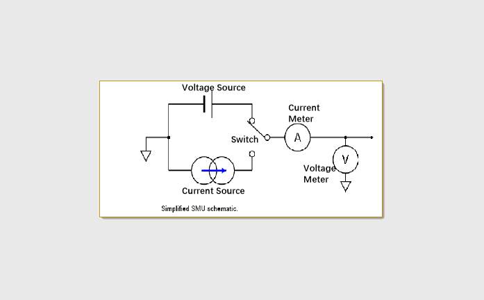
  • Five functions in one instrument

    Voltage source
    Current source
    Ammeter
    Voltmeter
    Electronic load
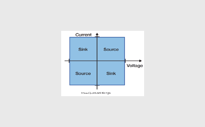
  • Quadrants I and III operate as a source: the actual polarity of the V/I output follows the source setting;
    Quadrants II and IV operate as a load: CC and CV work together; in load mode, the load setting polarity is opposite to the source polarity;
  • Tests a wide range of devices

  • Capture more measurement data

    ♦ 6½-digit resolution: accuracy comparable to a 6½-digit multimeter;
    ♦ 100 fA / 100 nV resolution: excellent sensitivity for both sourcing and measurement;
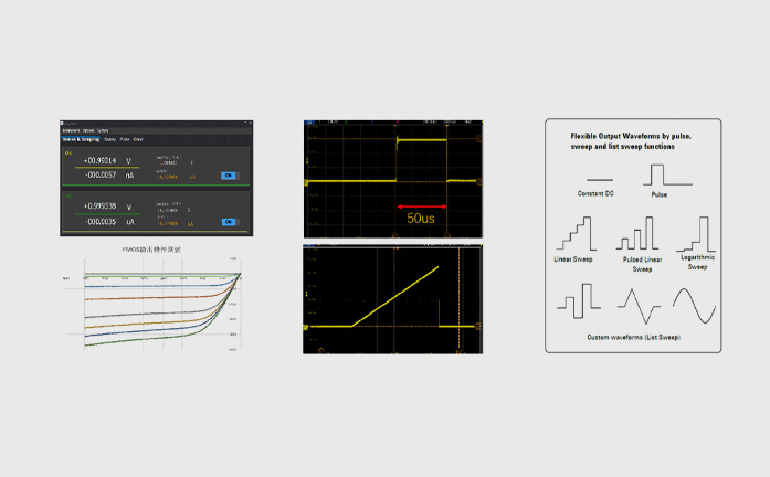
    ♦ 1 Msample/s: high-speed measurement with fast setup and digitization rates for arbitrary waveform generation and list sweeps;


Voltage source specifications


Voltage setting accuracy

RangeSetting resolutionAccuracy (1 year) ±(% reading + offset)Typical noise (RMS) 0.1 Hz-10 Hz
±200 V1 mV0.02%+30 mV1.5 mV
±20 V100 μV0.02%+2 mV160 μV
±6 V50 μV0.02%+500 μV36 μV
±200 mV1 μV0.02%+120 μV4 μV
Temperature coefficient±(0.15 × accuracy specification)/°C (0℃-18℃, 28℃-50℃)
Maximum output power per channel30W: ±20V@1.5A;30W: ±200 V@0.15A;18W: ±6 V@3A
settling time<800μs (typical)
Overshoot<±0.1% (typical, Normal, step is 10% to 90% of range, full-scale point, resistive load test)
Noise 10Hz-20MHz6V voltage source, 3A resistive load, <3 mVrms

[1] Accuracy calculation example: to test the accuracy of a 120mV output on the 200mV range, the tolerance is:

[2] This instrument has potentially hazardous high voltage (±210 V) output to the HI /Sense HI/Guard terminals. To prevent electric shock, relevant safety precautions must be taken before powering on. Do not connect the Guard terminal to any output, including shorting it to chassis ground or output LO, otherwise the instrument will be damaged


Current source specifications


Current setting accuracy

RangeSetting resolutionAccuracy (1 year) ±(% reading + offset)Typical noise (RMS) 0.1 Hz-10 Hz
±10 A150 μA0.4% + 40 mANA
±3 A15 μA0.05% + 2 mA40 μA
±1.5 A10 μA0.02% + 500 μA20 μA
±150 mA1 μA0.02% + 25 μA5 μA
±15 mA100 nA0.02% + 6 μA700 nA
±1.5 mA10 nA0.02% + 250 nA16 nA
±150 μA1 nA0.02% + 25 nA21 nA
±15 μA100 pA0.02% + 3 nA140 pA
±1.5 μA10 pA0.03% + 450 pA25 pA
±150 nA1 pA0.05%+250 pA5 pA
Temperature coefficient±(0.15 × accuracy specification)/°C (0℃-18℃, 28℃-50℃)
Maximum output power per channel30W: ±20V@1.5A;30W: ±200 V@0.15A;18W: ±6 V@3A
settling time<500 μs (typical)
Overshoot<±0.1% (typical, Normal, step is 10% to 90% of range, full-scale point, resistive load test)

1. The 1, 10A ranges support pulse mode only; accuracy is typical


Voltmeter specifications


Voltage measurement accuracy

RangeDisplay resolutionAccuracy (1 year) ±(% reading + offset)
±200 V100 μV0.02% + 30 mV
±20 V10 μV0.02% + 2 mV
±6 V1 μV0.02% + 500 μV
±200 mV100 nV0.02% + 120 μV
Temperature coefficient±(0.15 × accuracy specification)/°C (0℃-18℃, 28℃-50℃)


Ammeter specifications


Current measurement accuracy

RangeDisplay resolutionAccuracy (1 year) ±(% reading + offset)
±10 A110 μA0.4% + 25 mA
±3 A10 μA0.05% + 2 mA
±1.5 A1 μA0.02% + 500 μA
±150 mA100 nA0.02% + 25 μA
±15 mA10 nA0.02% + 6 μA
±1.5 mA1 nA0.02% + 250 nA
±150 μA100 pA0.02% + 25 nA
±15 μA10 pA0.02% + 3 nA
±1.5 μA21 pA0.03% + 450 pA
±150 nA2100 fA0.05% + 250 pA
Temperature coefficient±(0.15 × accuracy specification)/°C (0℃-18℃, 28℃-50℃)


1. The 10A range supports pulse mode only; accuracy is typical
2. For low-current measurement, it is recommended to use a triaxial cable: connect ForceHi to the center conductor, Guard to the inner shield, and the outer shield to protective ground; connect ForceLo to the center conductor, leave the inner shield unconnected, and connect the outer shield to protective ground. The rated insulation voltage of the coaxial cable must be no less than 250V.


Resistance meter specifications (4-wire)


Resistance measurement accuracy

RangeDisplay resolutiondefault measurement currentTypical accuracy (1 year)
±(% reading + offset)
1 Ω1 μΩ1.5 A0.073% +0.3334 mΩ
10 Ω10 μΩ150 mA0.057% + 3.334 mΩ
100 Ω100 μΩ15 mA0.08% + 33.34 mΩ
1 kΩ1 mΩ1.5 mA0.057% + 333. 4 mΩ
10 kΩ10 mΩ150 μA0.057% + 3.334 Ω
100 kΩ100 mΩ15 μA0.06% + 33.34 Ω
1 MΩ1 Ω1.5 μA0.06% + 333.4 Ω
10 MΩ10 Ω0.15 μA0.35% + 3.334 kΩ
100 MΩ100 Ω0.05 μA0.95% + 10 kΩ
Temperature coefficient±(0.15 × accuracy specification)/°C (0℃-18℃, 28℃-50℃)
Manual current source resistance measurement (4-wire)Total error=measured voltage/current source set current=resistance reading x (gain error percentage of voltage source range + gain error percentage of ammeter range + offset error of current source range/set current)+(offset error of voltage source range/set current value) Example: current source set current=1.5A voltage measurement range=6V total error=(0.02%+0.02%+500μA/1.5A)+(500μV/1.5A) 0.073%+0.3334mΩ


Pulse source specifications (4-wire)

Minimum programmable pulse width100 μs
Pulse width programming resolution1 μs
Pulse width programming accuracy±10 μs
Pulse width jitter2 μs
Pulse width definitionAs shown in the figure below, the time from the 10% leading edge to the 90% trailing edge


Pulse specificationsMaximum current limitMaximum pulse widthMaximum duty cycle
10.15 A/200 VDC, unlimited100%
21.5 A/20 VDC, unlimited100%
33 A/6 VDC, unlimited100%
43 A/20 V1 ms10%
510 A/6 V1 ms10%


Pulse source rise time (4-wire)

OutputRangeTypical rise time 1,3Typical settling time 2,3Test load


Voltage Source

200 V600 μs1.5 msNo load
20 V200 μs360 μsNo load
6 V160 μs300 μsNo load


Current source

10 A140 μs320 μsFull load
3 A120 μs280 μsFull load
1.5 A120 μs280 μsFull load
150 mA120 μs280 μsFull load
15 mA120 μS280 μsFull load
1.5 mA120 μS280 μsFull load


1. Time required for the pulse leading edge to go from 10% to 90%.
2. Time required for the pulse to reach within 1% of its final value.
3. Current source test is based on the 6V voltage range, with 105% full-scale clamp setting.


I-V output capability


Output settling time


Output


Range

Typical output settling time


Test conditions

Fast 1,2Normal 1Slow1


Voltage Source

200 V<1.3 ms<1.5 ms<2.5 ms


Time required to reach within 0.1% of the final value under open-circuit load conditions.

Step is 10% to 90% of range.

20 V<300 μs<360 μs<1 ms
6 V<150 μs<250 μs<1 ms
200 mV<200 μs<250 μs<1 ms


Current source

3 A<200 μs<280 μs<1.2 ms


Time required to reach within 0.1% of the final value under full-load conditions (0.3% for the 3A range).

The step is 10% to 90% of the range. 6V voltage range, 105% full-scale clamp setting.


1.5 A<200 μs<280 μs<1.2 ms
150 mA<200 μs<280 μs<1.2 ms
15 mA<200 μs<280 μs<1.2 ms
1.5 mA<200 μs<280 μs<1.2 ms
150 μA<250 μs<300 μs<1.2 ms
15 μA<250 μs<1.2 ms<2 ms
1.5 μA<600 μs<1.2 ms<5 ms
150 nA<600 μs<5 ms<12 ms


1. Output slew rate: Fast, Normal, Slow.
2. In Fast mode, the output may exhibit significant overshoot under different ranges or load conditions. For overshoot-sensitive devices, the Slow mode is recommended.


Sampling rate and NPLC settings


Configuration methodConfiguration range
NPLC0.00005 PLC ~ 10 PLC
Sampling Rate5 sps ~ 1 Msps


Looking for more sales, technical and solutions information?

Contact Us >

Leave a Message

Hotline

0731-8526092618665876229

We will get back to you as soon as possible. Thank you!
(Jectronic handles your information with care. By submitting, you confirm that you have read and agree to the personal information transfer statement of this website.)

Inquiry Type: Message