Quick Contact>

Hotline

0731-85260926 18665876229

中文
Power Transistor Curve Tracer Semiconductor Parameter Analyzer SMU Source Measure Unit Dynamic Parameter Test System CV Parameter Tester Gate Charge (Qg) Tester WAT Wafer Acceptance Test System TLP Transmission Line Pulse EMMI Low-Light Infrared Fault Localization HCI/BTI/TDDB/EM effects Femtoammeter/Electrometer/High Resistance Meter High and low temperature electrical performance simulation H3TRx Customizable System Integration Software
Standard Manual Probe Station Portable Desktop Probe Station Semi-automatic probe station RF/Microwave Probe Station High/Low Temperature Probe Station Vacuum cryogenic probe station system Wafer electrical parameter test system Strong Magnetic - Hall Probe Station Custom Precision Probe Card High/Low Temperature Chuck System (Taiko) Magnetic Probe Holder CCD Microscope Test cables and adapter fixtures Shielded Box and Vibration Isolation Table Probes and other accessories
B-H Analyzer Magnetic Loss Power Tester Impedance Analyzer DC Bias High-Frequency LCR Meter Vector Network Analyzer VNA Frequency Response Analyzer Milliohm Meter / Battery Internal Resistance Tester
Rapid Temperature Change Thermal Flow Meter Device High/Low Temperature Platform Thermalplate Device junction temperature simulator Tj
12-bit high-definition digital oscilloscope Optically Isolated Oscilloscope System Basic Digital Oscilloscope Signal generator Digital Multimeter DMM Spectrum Analyzer Frequency counter Infrared thermal imager
Optically isolated voltage probe Optically Isolated Current Probe Dynamic On-Resistance Rds(on)dynamic Oscilloscope voltage probe High-voltage differential probe Fluxgate current transformer AC/DC Current Probe Non-inductive coaxial shunt Communication Interfaces and Cables Dedicated fixture Software
Multi-channel data acquisition instrument Data Acquisition and Playback Power Analyzer
Digital Phase-Locked Loop Amplifier Ultra-Low Noise Preamplifier Precision Current Amplifier Precision Differential Amplifier Precision Filter Light chopper Precision Low-Noise DC Power Supply
Programmable DC Power Supply DC Electronic Load Precision Bipolar Power Amplifier Bipolar simulation power supply
Safety Tester (ACI/DCI/IR/GB) High-voltage meter HV meter
Standard or calibration source meter Standard current and voltage meters
Products
SSI Small-Volume 120kHz Lock-In Amplifier OE1201

SSI Small-Volume 120kHz Lock-In Amplifier OE1201

Model:OE1201      Country of Origin:China

Category:Digital Phase-Locked Loop Amplifier

Overview:
50 mHz to 120 kHz measurement bandwidth
1 nV to 1 V voltage measurement range
Compact and easy to integrate
Performance comparable to the SR830
Best value for money


Features
Specifications
Application Notes
Functions & Configuration

Input Signal Channel

         The OE1201 digital lock-in amplifier employs a new-generation low-noise analog preamplifier design that handles both differential and single-ended signals, with an equivalent input noise of less than 9 nV/√Hz. The input impedance of this channel is as high as 10 MΩ, enabling accurate detection of levels from 1 nV to 1 V at full-scale output. In addition, the OE1201 front end can be set to current gains of 106 or 108 V/A, making it suitable for measuring weak current signals in the nA and pA ranges. The OE1201 also features two high-performance notch filters (centered at 50/60 Hz and 100/120 Hz) to suppress power-line interference. The OE1201 achieves a dynamic range of more than 100 dB and automatically adjusts its internal programmable gain amplifier according to the input signal amplitude to change the overall dynamic reserve of the system.


Reference Signal Channel

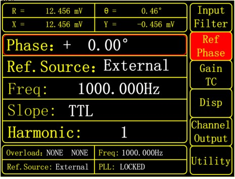
         The reference signal of the OE1201 digital lock-in amplifier can be flexibly selected according to the user's needs, divided into external reference and internal reference. When the OE1201 is set to internal reference mode, the instrument's high-precision oscillator and digital synthesis algorithm generate the sine wave used to multiply the input signal, and the internal reference signal is virtually immune to phase noise. Using digital phase-shifting technology, the phase of the internal reference signal can achieve a resolution of 0.01°. The internal reference mode operates over a frequency range of 50 mHz to 120 kHz. When the OE1201 is set to external reference mode, sine wave signals and TTL logic levels can serve as the external reference. The rising or falling edge of the external reference signal triggers the internal phase-locked loop (PLL). Based on the reference signal frequency, the OE1201 can detect signal harmonics, with the maximum detectable harmonic frequency being 32,767 times the fundamental frequency, provided the maximum harmonic frequency does not exceed the instrument's operating frequency of 120 kHz.


Display

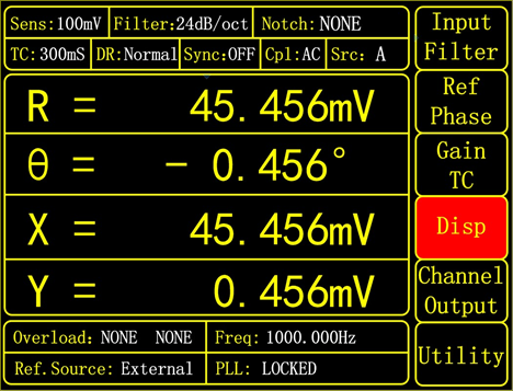
         The OE1201 uses a 3.5-inch 320×240 TFT color display as its main screen, providing clear, intuitive viewing of settings and measurement results such as signal X, Y, R, and θ values.

image


Oscillator

         The internal oscillator of the OE1201 lock-in amplifier delivers a low-distortion (–80 dBc) reference signal. The single-sine reference signal is tunable from 50 mHz to 120 kHz with a frequency resolution of 0.1 mHz. The frequency and amplitude of the internally generated reference signal can be set via the front panel or through computer communication. When the instrument operates in external reference mode, the internal oscillator remains phase-locked to the external reference signal.

image


Signal Generator

         Built around a 16-bit DAC, the OE1201 generates sine waves from 50 mHz to 120 kHz. The amplitude and phase of the output are referenced to the instrument's internal oscillator, and the amplitude can be set from the instrument's control menu. The maximum sine wave amplitude from the OE1201 signal generator is 1 Vrms.


Simple, Intuitive Operation

         All OE1201 functions are selected using the front-panel knob and left/right keys, while the corresponding parameters are set directly with the setup keys in the right-hand column. The instrument ships with a free LabVIEW program that provides full access to all OE1201 measurement functions, including setting appropriate control parameters and reading and saving measured data. This makes the OE1201 easy to integrate into complex scientific experiments. The LabVIEW interface displays all control commands and the instrument's responses.


Signal channels
    Voltage input mode            Single-ended or differential input
    Full-scale sensitivity            1 nV to 1 V, in 1-2-5 sequence steps
    Current input gain            106 or 108 V/A
    Input impedance
        Voltage                10 MΩ//25 pF, AC or DC coupling
        Current                1 kΩ to virtual ground
    Common mode rejection ratio              >100 dB (within 100 kHz), >90 dB (beyond 100 kHz)
    Dynamic reserve                >100 dB
    Gain accuracy                0.2% typical, 1% maximum
    Voltage noise
        at 997 Hz            9 nV/√Hz
    Current noise
        At 97 Hz             0.13 pA/√Hz
        at 997 Hz            0.14 pA/√Hz
    Line frequency filter              50/60 Hz and 100/120 Hz
    Input shield grounding            BNC (A/I, B) shield can be directly grounded or connected to floating ground via a 10 kΩ resistor

    Stability                  2 ppm/℃


Reference channel
    Input
        Frequency range            50 mHz to 102 kHz
        Reference Input            Square wave or sine wave
        Input Impedance            1 MΩ//25 pF
    Phase
        Resolution              0.01°
        Absolute Phase Error        <1°
        Relative phase error        <0.01°
        Orthogonality
            Internal reference        Synthesized, at 1 kHz: <0.0005°rms
            External Reference        At 1 kHz: 0.01°rms (time constant 100 ms, 12 dB/oct)
        Temperature Drift
            Below 10 kHz     <0.01°/℃
            Above 10 kHz     <0.1°/℃

    Acquisition time

        Internal reference            Real-time acquisition

        External Reference            (10 cycles + 40 ms) or 100 ms


Display

    Screen                    3.5-inch, 640×480 TFT color LCD screen

    Screen format                Single-channel or dual-channel display

    Displayed values                  Each channel can display X, Y, R, and θ values

    Display types                Numeric display, bar graph, XY plot and polar plot

    Color styles                Yellow, green


Auxiliary inputs and outputs

    CH1 and CH2

        Function                Output X, Y, R, θ and harmonics

        Amplitude                ±10 V

        Drive current            ±30 mA max


Communication interface

    RS-232 to USB             RS-232 to USB 2.0 interface

    RS-232 interface              Standard 9-pin RS-232 male connector

    IEEE-488 Interface (optional accessory)


Others

    Power Requirements

        Voltage                100~240 V AC

        Frequency                50/60 Hz

        Power                10 W typical, 20 W maximum

    Power supply noise rejection            70 dB@1 MHz

    Weight                    3.2 KG

    Dimensions

        Width                  259 mm

        Depth                  320 mm

        Height

            Including feet        115 mm

            Excluding feet      102 mm


Looking for more sales, technical and solutions information?

Contact Us >

Leave a Message

Hotline

0731-8526092618665876229

We will get back to you as soon as possible. Thank you!
(Jectronic handles your information with care. By submitting, you confirm that you have read and agree to the personal information transfer statement of this website.)

Inquiry Type: Message